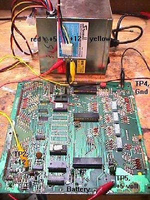
- TP5 = +5 volts (right next to the battery). Red power supply lead.
- TP4 = GND (opposite end of the board from the battery). Black power supply lead. Don't get this confused with TP1, which is right next to it!
- TP2 = +12 volts (on the same side of the board as the battery; don't get this confused with TP3, which is right next to it!). Yellow power supply lead.
- TP3 = +21.5 volts (right next to TP2). No power supply lead since neither a computer power supply or a switcher supply this voltage.
- The reset circuit is damaged (after all, it's in the battery corrosion area!). This includes transistors Q1 and Q2 (both 2N3904), Q5 (2N4403), and diodes CR5 (1N4148 or 1N914) and VR1 (1N959B or 1N4738A).
- The program ROM (read only memory) at U6 is bad.
- The ROM jumpers are incorrectly set for the U6/U2 ROMs installed.
- The U9 CPU microprocessor is bad.
- The U11 PIA (peripheral interface adapter) is bad.
- ANY of the sockets for chips U6, U9, U11 are bad.
- With the MPU board OFF, Put a logic probe or DMM set to DC volts on pin 40 of the U9 CPU. The logic probe will be "low" (or the DMM at zero volts).
- Power the MPU board on.
- In just an instant, the U9 CPU Pin 40 should go "high" on the logic probe, or about 4.75 to 5.5 volts on the DMM. Repeat this for U9 pin 2, which also should also go high.
- With the MPU board powered on and pin 40 of the U9 CPU high (4.75 to 5.5 volts), short the junction of resistors R1 and R3 to ground. To do this, find the junction where resistors R1 and R3 connect together. With the MPU board on, use a wire and short this junction to ground (TP4).
- U9 CPU pin 40 should now go low to zero to .5 volts while the R1/R3 junction is grounded.
- U9 pin 3 = 2.4 volts
- U9 pin 36 = 2.6 volts
- U9 pin 40 = 4.75 to 5.5 volts
- U9 pin 5 = 2.8 volts
- Q1,Q2 - Transistor, 2N3904
- Q5 - Transistor, 2N4403
- VR1 - Diode type 1N4738A, Zener, 8.2V (alternate for 1N9598)
- CR8 - Light Emitting Diode, Green.
- CR5,CR7 - Diode, Switching. 1N4148
- CR44 - Diode, Rectifier. 1N4004 (or better)
- C1,C2 - Capacitor, 820pF, Axial Ceramic.
- C5 - Capacitor, 4.7uF, Radial Tantalum.
- C3,C13,C80 - Capacitor, 0.01uF, Axial Ceramic.
- R1,R3,R24,R28 - Resistor, 8.2K, 1/4W, 5%
- R2 - Resistor, 120K, 1/4W, 5%
- R11 - Resistor, 82, 2W, 5%
- R12 - Resistor, 270, 1/4W, 5%
- R16 - Resistor, 2K, 1/4W, 5%
- R17 - Resistor, 150K, 1/4W, 5%
- R29 - Resistor, 470, 1/2W, 5%
- R107 - Resistor, 3.3K, 1/4W, 5%
- R112 - Resistor, 1K, 1/4W, 5%
- R134 - Resistor, 4.7K, 1/4W, 5%
- R140 - Resistor, 20K, 1/4W, 5%
- DS1811-15 = 4.13v
- DS1811-10 = 4.35v
- DS1811-5 = 4.62v
3a. When things don't work: Making a MPU Test Fixture.
-
If your game is not working, chances are the MPU board is at fault. To fix
the board, you'll have work on it on your bench, then install it in the
game to test it. I found this too tedious when doing MPU repairs. Instead,
I constructed a simple test fixture I would use to test the MPU board right
on my workbench.
The J4 MPU Board Connector.
If you don't want to make a work bench test fixture for repairing
your Bally MPU board, there is an easy way around this. Assuming
your Bally power supply is working correctly in your game, when testing a Bally
MPU board, you only need to use connector J4 on the MPU board.
The J4 connector is the power connector. With it only attached and
a working power supply, you can quickly test your Bally MPU right in the game.
Making a Test Fixture.
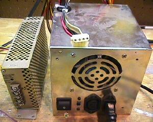
To make a test fixture, you will need some sort of power supply that will
deliver +5 and +12 volts. You can buy a video game switching power supply
(about $25), or you can use an old computer power supply. Either will work
fine. Old computer power supplies are plentiful, and often $15 or less, used.
|
On the left is a video game switching power supply. On the right is a used computer power supply. Either will work fine for a test fixture. Note the computer power supply connector on top of the box is the one that will supply our +5, GND and +12 volts. This plug was used to power drives (hard drive, CD rom, etc). Red is +5, black is GND, and yellow is +12. |
|
-
In either case, all you need to do is connect the power supply
to a wall plug (110 vac), and put aligator clips on the GND,
+5 vdc and +12 vdc. That's all you need to power up a Bally MPU
board on your workbench!
On a computer power supply, the best way to do this is to use one of the plugs that connected to the computer's hard drive, floppy drive, or CD ROM drive. There are usually at least three of these 4 pin plugs on each computer power supply. These plugs have two black wires, and one red and one yellow wire. The two black wires are ground, the red wire is +5 vdc, and the yellow wire is +12 vdc. I used some crimp-on male connector pins and jammed them into the plug. Then I connected these to aligator clips, which ultimately go to your MPU board.
|
Using a computer power supply on the workbench to power a Bally MPU board. |
|
-
On the MPU board, the test points to connect the aligator
clips to are:
Once you have your test fixture constructed, you can diagnose Bally MPU problems with the flashing LED on the board easily. Instead of putting the board back in the game to test it, just turn your power supply on and count the flashes!
-
Warning!!
Be careful when you hook up the voltages to your MPU board. If you short +12 volts to +5 volts (for example), you will probably destroy all the chips on the MPU board! Also be careful when you hook up +12 volts to TP2. It is VERY easy to short TP2 to TP3. This may damage the MPU board too! (Unlikely, but let's not risk it). So be careful, and double check your connections before you turn the power supply on.
|
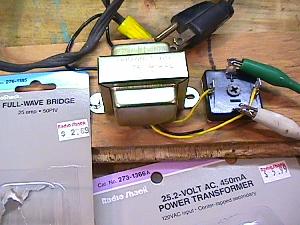
To get the last flash from the MPU board, 20 to 25 volts DC is needed at test point TP3 on the MPU (or put a temporary alligator jumper wire from chip U12 pin 3 to U14 pin 14). This can be done by purchasing an inexpensieve 25 volt transformer and bridge rectifier. I screwed this make- shift power supply to a board for easier use. |
|
-
The Last LED Flash (missing voltage at TP3).
Using the above jig to power a MPU on your workbench will NOT get the last MPU LED "flash" in the power-on sequence. This happens because there is no +43 volts DC present (as used for the solenoids) on the MPU board, which has a circuit to detect this voltage. For most games, this means only getting 6 of the 7 total flashes (for a working MPU). The exception to this is Baby Pacman and Granny and the Gators, which only get 5 of the 6 total flashes. And since the last flash is not achieved, the board won't go into full attract mode.
There are *two* ways to solve this problem. The first is to trick the MPU board into thinking the 43 volts is present. To do this, put a temporary jumper wire on the MPU board, connecting chip U12 pin 3 to chip U14 pin 14. This can be done easily with an alligator jumper wire, connecting the top leg of resistor R23 (leg closest to chip U12) to the top leg of resistor R17 (leg closest to TP3). This is certainly the easiest approach.
The other solution is more realistic, but involves some parts (a transformer and a bridge rectifier). Radio Shack sells a 120 volt AC to 25 volt AC transformer (#273-1366) for $6 that works well for this. They also sell a 25 amp 50 volt bridge (#276-1185) for about $2.70, which is also needed.
To wire this up, connect the two black transformer wires that are together on one side of the transformer to a 120 volt power cord. The remaining three wires (two yellow, one black) on the other side of the transformer are the output. Connect the two yellow wires to the AC terminals of the bridge. The black (center tap) transformer wire you won't use. The bridge should have a label signifying at least one AC lead. The second AC lead is diagonal or across from the labeled lead.
|
The J4 connector of the MPU board. Notice the TP3 and TP2 test points at the upper right corner of this picture. The R113 resistor takes the +43 volts from J4 pin 15 and lowers it to +21.5 volts at TP3. |

|
-
Another lead on the bridge should be labeled "+". This is the
positive DC voltage output lead. The lead opposite or diagonal
to this terminal is the negative DC lead. Connect the "+" lead
to the MPU's test point TP3 (which is right next to TP2).
Connect the negative bridge lead
to ground (TP4) on the MPU board.
The output from the bridge will be about 25 volts DC. 43 volts DC is not needed because this connects 25 volts to the MPU board's TP3 test point, which is looking for 21.5 volts DC. What happens is the 43 volts DC comes from the rectifier board and goes to MPU connector J4 pin 15. Then the 43 volts goes through resistor R133, which lowers the voltage to 21.5 volts. Then a "zero crossing" voltage detection circuit looks for that 21.5 volts. If present, a working MPU board will flash the last time. If the voltage is missing, there is no last LED flash.
So instead of supplying 43 volts to connector J4 pin 15, we just skip resistor R133 and connect our 25 volt DC power supply directly to TP3. It's pretty easy to get a 25 volt transformer, but getting a 43 to 50 volt transformer is more difficult. The zero crossing circuit will work fine if you supply 25 volts DC (instead of 21.5 volts) to test point TP3.
The voltage supplied above with the transformer and bridge gives 25 volts DC to test point TP3. This DC voltage is NOT smoothed with a filter capacitor! This is done for a reason. The original Bally power supply doesn't filter this voltage, and for good reason. The zero crossing circuit requires the DC voltage "ripple" to work!
(Re-)Booting a MPU Board with the Test Fixture.
After connecting the test fixture to the MPU board, simply
turn the power supply on and count the LED flashes. To
re-boot the MPU board, simply short together (with a screwdriver blade)
pins 39 and 40 of the U9 CPU.
This will quickly reset the CPU, and the flash sequence will start over, without
having to turn the power supply off.
3b. When things don't work: Fixing the MPU (LED flashes and the such).
-
I am assuming if your MPU board had any battery corrosion,
that you have fixed it (see the Removing the MPU Battery
and Fixing Corrosion section). Fixing a MPU board with corrosion
is like a dog chasing its tail; a never ending path of frustration.
Corrosion can cause intermittent problems. Take care of the corrosion first
before trying to fix a MPU board.
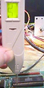
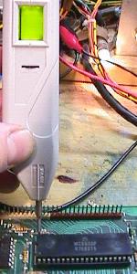
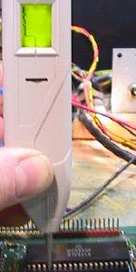
Fixing a Bally MPU board, generally speaking, is one of the easiest game boards you will ever repair. The reason for this, is Bally uses a "LED flash test". The green LED (light emitting diode) lamp is right next to the battery on the MPU board. As the MPU board boots, it does self diagnostics. For each diagnostic test the MPU board runs, it flashes the LED when that diagnostic is complete. If a diagnostic fails, the boot up process stops, and the LED stops flashing. There are a total of 6 or 7 LED flashes during the boot-up process. This makes determining MPU board problems fairly easy.
First Step: Count the LED Flashes.
The first step in fixing a non-working game is to count
the LED flashes. On a working MPU board, when you turn
the game on, the LED should "flicker" (a very faint and
quick flash), and then flash seven times (only six times on
Baby Pacman or Granny and the Gators). If the board does
not do this, the internal diagnostics have determined
a problem. At this point you should remove the board
from the game, and hook it up to your test fixture (which
you made above in the Making a MPU Test Fixture
section). Working on your MPU board on a workbench is much
easier than trying to fix it, and then test it in the
game itself.
The Last Flash.
If you game does the initial flicker, and then follows with
all the flashes but the last flash (flash number seven, or flash
six on Baby Pac/Granny), check your +43 volt solenoid power F4
fuse on the rectifier board before proceeding. This last flash
verifies that the game has +43 volts for the solenoids. If it
doesn't (the F4 fuse is blown), the game won't boot and won't
finish the flash sequence.
No Flashes: the LED is Permanently On.
If you turn your Bally game on, and the LED stays on
continually, this is one of the hardest problem to
fix on these boards. A stuck on LED can be caused by
any (or all!) of the following:
The first and last points are probably the most common problems.
Go "Bare Bones" (What to Remove for the first "Flicker").
To get the initial flicker out of the MPU board's LED,
you only need three chips on the MPU board. These three
chips are U9 (the CPU), U11 (PIA) and U6 ROM (except on
some Stern games, which also require the U2 and/or U5/U6 ROMs).
Remove all other socketed chips! Once you get the initial
flicker out of the MPU board, then you can re-install the
other removed chips.
The Reset Circuit.
If the reset circuit is damaged, the MPU board will never
start, and the LED will stay on at power up.
Since the reset circuit is in the "corrosion zone",
it is often damaged from battery corrosion.
The reset circuit holds pin 40 (reset) of the U9 CPU
low until +5 volts is "stable", and then sets pin 40 high
(telling the CPU it can start the boot up process).
While the reset section is holding pin 40 of the CPU low,
the LED will be on. This is one part of the initial "flicker" seen
when a working Bally board is first powered on.
Here's what to try first:
If the above happens, the reset circuit is probably working fine. If pin 40 of the CPU is low and never goes high, there is a problem with the reset circuit. Since pin 40 never goes high, the CPU will never start the boot process, and the LED will stay on.
Here's some other stuff to try:
The above procedure is simulating what the reset circuit is meant to do. If shorting the junction of R1 and R3 does not pull U9 Pin 40 from high to low, then there is a problem with the reset circuit. Most likely there is a problem with Q1 (2N3904), Q2 (2N3904) and/or Q5 (2N4403). Replace them all (they are cheap!) and repeat the above procedure. Also check/replace diode CR5 (1N4148 or 1N914). Finally check/replace diode VR1, which is a 1N959B (1/2 watt) or 1N4738A (1 watt), 8.2 volts (note VR1 is mis-labeled in the manual as "1N9598"). If you still can't get U9 CPU pin 40 to go low, there is some other problem in the reset circuit (corroded traces?).
Here are some other points to check. Turn the MPU board on and test:
If the above voltages check out, then the reset section is probably working correctly. This means your problem probably lies with chips U6, U9 or U11 (or their sockets), or incorrect MPU board jumpers.
A Reset Trick (LED stuck On) - Adding a Capacitor.
If having problems with the reset (LED stuck on),
try shorting together (with a screwdriver blade)
pins 39 and 40 of the U9 CPU. This will manually reset the CPU, since
reset pin 40 gets set low by ground, pin 39.
Essentially, the screwdriver blade is doing what the reset does.
So if the flashes start and proceed, there is a problem with the reset
section of the MPU board.
It could be the +5 volts is not stablizing within the "window" the CPU expects (about 50ms). To make the reset window longer, try putting a 470 mfd electrolytic capactor in the reset section (on the solder side of the MPU board). Solder the positive leg of this cap to the collector (top leg) of Q1. Then solder the negative leg of the cap to ground (the emitter of Q1). This will increase the reset timing length. Now test the MPU board. If the MPU board works and continues with the flashes, the +5 volts was just not getting "stable" in the 50ms window (there could be a power supply problem, probably with the large 5 volt rectifying capacitor on the driver board).
One note about this added reset capacitor. Since the 470 mfd cap increases the reset timing (the time pin 40 of the CPU is held low), the initial "flicker" may not longer be a "flicker". The LED will stay on longer (because the reset is longer), making the "flicker" more of a "flash".
Buy a Bally Reset Section Repair Kit.
Having problems with the reset section on your Bally board?
Instead of ordering all the parts separately, I suggest just buying a "Bally
Battery Corrosion Repair Kit" BALLY35-BA-KIT from
Ed Krzycki (gpe@cox.net).
This kit includes all the resistors, capacitors, diodes, transistors and chips typically
gone bad in the reset section. For a mere $10, or $4.50 (without a 5101 RAM chip),
this kit is well worth it. See Ed's web page at
members.cox.net/gpe/GPE_Kits.html
for more information. When buying the kit, install *all* the parts,
even if the originals "look good".
If for some reason the $4.50/$10 is too much money, here are the typical parts needed for reset section repair:
Using a Dallas/Maxim DS1811 in the Reset Section.
There is also another way to fix the reset section.
This involves using the new Dallas/Maxim Semiconductor D1811 reset chip (TO-92 package).
This single reset chip should replace a whole bunch of
the stock reset components on a Bally MPU (I am working on
exactly what can be removed!)
This inexpensive Dallas device looks like a transistor, but is really a three leg chip in a TO-92
transistor package (I also show how to use this same reset chip on Gottlieb
System80 MPU boards in the Gottlieb System80 Repair Guide). Click
here or
here (PDF, more info)
for the specs on this chip. Cost is less than $1, and can be ordered directly
from Dallas/Maxim Semiconductor at
www.dalsemi.com
via their phone number 888-629-4642 (but orders must be faxed in at 408-222-7174).
Be sure to order the TO-92 package (part number DS1811-10), as this
chip also comes in a surface mount SOT23 package.
Interestingly, the new Alltek Systems replacement MPU board (allteksystems.com) also uses a Dallas-Maxim reset chip. The only difference is their board uses a DS1233 (which is the same as the DS1811, except the reset timing is 250ms, where the DS1811 is 150ms).
The Dallas DS1811 comes in three TO-92 flavors of "normal reset threshold":
The DS1811 is installed with pin 1 going to /RESET (Q5's leg closest to resistor R11), pin 2 to +5 volts, and pin 3 to ground. In the future I will be adding more information on what reset components can be removed installing the Dallas DS1811. If the MPU board boots fine by shorting pins 39 and 40 of the U9 CPU, installing this part may be the "quick fix" to your reset problems. Also the benefit of removing many of the stock reset components on boards with battery corrosion certainly helps.
There is a side affect of the changed reset circuit: Since the Dallas DS1811 increases the reset timing (the time pin 40 of the CPU is held low) from about 50ms to 150ms, the initial "flicker" may not longer be a "flicker". The LED will stay on longer (because the reset is longer), making the "flicker" more of a "flash".
A "Good" U6: EPROMs, Masked ROMs, and Jumpers.
If the LED is stuck on,
next give yourself the advantage of knowing that at least the program jumpers
match the type of Game ROMs being used (EPROMs, Masked ROMs,
etc.). Jumper are discussed in the Game ROMs, EPROMs,
and Jumpers section below. Basically these jumpers tell the
MPU board what type, size, and how many game ROMs are being used on the
MPU board. Bally did this as a convenience factor; if you wanted
to use an older MPU board in a newer game (that had a larger program and
hence larger or more ROMs), you could. All you needed was to change
the jumpers. It also allowed you to use the board with EPROMs (erasable,
programable read only memory), or factory created "masked" ROMs. The
factory masked ROMs are black with numbers screened on them. These
are not re-programable, and must be used in the game they are
intended for. EPROMs on the other hand, can be re-programmed and
re-used (if you have an EPROM programmer, which costs about $150
and can connect to your computer).
An accurate jumper chart is mandatory here and a basic knowledge of
how to recognize the different types of ROMs is also a plus.
U6 is the program ROM chip which contains the code for the boot-up diagnostics (and on some Stern games, U2 and/or U5/U6 ROMs are also required for the initial "flicker"). If you don't have a good U6, and don't have the MPU jumpered properely for that U6/U2, the diagnostics can't even start to run. If you don't have an EPROM programmer to make your own U6 EPROM, contact Tom Callahan and order the ROMs needed for your particular game. Make sure you plug them into the sockets correctly (notch oriented correctly) when you install them. Also make sure you have the jumpers set correctly for the type of ROMs you are installing.
Don't Change the MPU board's ROM jumpers unless you have to!
If the U6/U2 ROM jumpers are incorrectly set on your MPU board,
this can cause a locked-on MPU board LED. For this reason,
I suggest not changing the MPU board jumpers until getting
the intial flicker from the LED. If the jumpers are changed,
TWO problems could exist instead of just one! If
not sure if the U6 ROM is good, try and install a known good ROM
of the same type (or test the U6 ROM in another game).
This way the board jumpers don't need to be changed.
Using 2532 EPROMs instead of 9332 Masked ROMs.
If the game in question is a later Bally game with 9332 masked
ROMs, these can be changed to 2532 EPROMs with NO jumper modifications!
This can be handy and convenient if the original black 9332 masked
ROMs need changing, but the repair person doesn't want to mess
with the jumpers.
A "Good" U9 and U11.
These two chips MUST also be good to get your MPU board to
even start to work. The diagnostics won't even start to run
if you don't have a good CPU chip at U9. Also a good PIA chip
at U11 is required.
If your LED is locked on, and the reset circuit is working (see above), I would next invest in a new 6800 CPU for U9, and a new 6821 PIA for U11. You can buy these from Jameco (800-831-4242) for just a few dollars. Get a couple extras of each chip. While you're ordering them, get a few 5101 RAM chips too (as these go bad a lot on the MPU board).
What Chips are Required to Get the MPU "Unlocked"?
The only socketed chips that are required to get the MPU board
to do its first flicker, are a working U6 (program ROM), U9 (the CPU),
and U11 (a PIA). Of course this assumes the reset circuit is working
properely. All other socketed chips can be removed
until the board becomes "unlocked" and does its first flicker.
How Can I Ensure I have good U6, U9 and U11 Chips?
I keep a working MPU board around, and plug the unknown
chips (one at a time!) into the working MPU. Then I power the
MPU on and see if it still works. This works best for me,
but you may not have a good MPU spare laying around.
If you have no spare working MPU, make sure you buy some new U9 (6800 CPU) chips and U11 (6820 PIA) chips from Jameco. They are inexpensive and worth keeping "in stock". And get a set of known good EPROMS (U6/U2) too. You can buy these from Tom Callahan if you don't have an EPROM programmer
Good Chip Sockets (replace the "brown" sockets!).
If the sockets that U6, U9 and U11 plug into are "bad", nothing will
make the LED start flashing until this is fixed. If your sockets are
the "brown" variety, or have the brand name "SCANBE" or "RS" impressed
in the sockets, replace ALL of them! These types of sockets are known
to be troublesome. Another approach to replacing these problem sockets
is to plug a new machine pin socket into the problem socket, then
plug the chip into the new socket. This is
a good temporary solution until you get the MPU board working.
Then you can later replace the old bad sockets with new machine pin sockets.
Using your DMM, buzz-out the chip legs to the under side of the MPU board
to make sure the sockets are good.
Note: do NOT get gold plated sockets! These react with the different metal in
the chip legs, and can cause intermittent problems. Also remember that U11
is in the "corrosion zone". This means this socket could have easily
been affected by battery corrosion.
Re-seating the Chips.
Sometimes fixing a MPU board can be as easy as taking all the socketed
chips out, and re-seating them into their sockets. It's worth a try,
as it only take a minute (and costs nothing). Sometimes bad connections
can be rectified by doing this. Make sure when you plug the chips back
in, that ALL the legs go into the socket and that the chip notch is oriented
in the correct direction (a common neophyte error). Plugging a chip in
"backwards" usually destroys it. If re-seating the chips does work, this
usually means the sockets will need replacing. If the problem keeps
coming back, I would suggest replacing the socket(s) in question.
|
Component layout on the Bally MPU. |
|
- If the zener diode VR1 (1N959B or 1N4738A, 8.2 volt) on the MPU board is bad, the LED will remain on.
- If the reset transistors Q1 (2N3904) and Q5 (2N4403) are damaged, the LED will remain on. As a general rule, it's always a good idea to replace these inexpensive transistors.
- If diode CR5 (1N4148 or 1N914) is bad, the LED will remain on.
- If transistor Q2 is bad, it could leave the LED on (regardless of what the MPU is doing!).
- If your CPU board has brown sockets, or sockets labeled "SCANBE" or "RS", you may want to replace ALL the sockets. These sockets are known to be problematic. An alternative to replacement is to plug a machine pin socket into the problem socket, then plug the chip into the new socket. This is a good temporary solution until you have the MPU board working.
- Measure the voltage at the CPU board. Even if you are
using your test fixture, measure the voltage right at the
chips to verify. The +5 line should be 4.8 to 5.2 volts DC.
Check the power at the required socketed chips (U6, U9, U11). This will tell
you if power is getting through the board to the chips
- U6, U2 (ROM): +5 = pin 24, GND = pin 12
- U9 (CPU): +5 = pin 8, GND = pin 1 or 21
- U11 (PIA): +5 = pin 40, GND = pin 1
- U8 (5101): +5 = pin 22, GND = pin 8
- U7 (6810): +5 = pin 24, GND = pin 1
- Using a logic probe, check U9 (CPU) pin 2 and pin 40. They should be high. Pin 40 is the Reset line, and this pin will start LO at initial power-on (for about 50 ms), and then go HIGH. As you turn the power on, the logic probe's Lo LED should light briefly, then the Hi LED should turn on and stay on. If there is no intial LO followed by about 4.5 volts at pin 40, the "valid power" reset circuit in the lower left corner of the board is at fault. The reset section's job is to hold the CPU pin 40 Lo until the +5 volts stablizes, and then allow pin 40 to go high to 4.5 volts. If pin 40 stays low, the board will never reset, and the LED will stay locked on. Most likely there is corrosion damage to transistors Q1 (2N3904), Q2 (2N3904), and Q5 (2N4403). Also check diode CR5 (1N4148 or 1N914). Replace all of these if you suspect them as bad. Or better yet, order a reset rebuild kit from Ed (about $10) at members.cox.net/gpe/GPE_Kits.html, and rebuild the entire reset section.
- If U9 CPU pin 40 is high (about 4.5 volts), then jump the junction of R1 and R3 to ground. Now check U9 CPU pin 40 again. This pin should be low (about .5 volts). This is simulating what the reset section does at power-on. If jumping R1/R3's junction to ground does not give .5 volts at U9 pin 40, there is still a problem with the reset section. Try replacing the reset transistors Q1 (2N3904), Q2 (2N3904), and Q5 (2N4403). Also check the diode CR5 (1N4148 or 1N914). To do this, put your DMM on diode setting. You should get a reading of .3 to .6, and reading of null (zero) when the leads are reversed. Or again, install one of Ed's reset section rebuild kits (which includes all the reset parts needed).
- Using a logic probe, make sure chip U9 (the CPU), pins 3 and 36, 37 are "pulsing". These are the "clock" signals. If you don't have a logic probe, put your DMM on these pins and you should get about 2.5 volts (the average of the pulsing waveform). If you don't have a pulse or about 2.5 volts, suspect chips U15 (MC3459L or 74S37) and U16 (9602 or NTE9602). Also sometimes the C14 and/or C15 (470 pf) capacitors have failed. However the most common cause is a bad U15.
- Check that U9 (CPU) pin 2 is high (+5 volts). This is the Halt signal on the CPU. If it's not HIGH, check for a broken or missing resistor at R135 or a short on the J5 connector.
- Using a logic probe, check that U9 (CPU) pin 5 is pulsing (or use your DMM and you should get about 2.8 volts). This is the VMA (valid memory address), and is an output from the CPU. If it's not pulsing, the CPU is not running! It could be a bad U9 chip, or some fault on the address and/or data lines cause U9 to "crash". Watch U9 pin 5 on the logic probe after turning the power off and then back on. You should see it pulse for a second or two before stopping. If any CPU output pin is shorted, this can cause the CPU to crash.
- Trace the VMA signal through its path. Using a logic probe, test
the following path. You should get a pulsing signal at all points
while the game is in attract mode (or when the MPU is on the bench
in your test fixture):
- U9 pin 5 (VMA line on the CPU): Pulse
- U19 pin 8 (input to U19): Pulse
- U19 pin 9 (input to U19): HIGH
- U19 pin 10 (output from U19): Pulse
- U14 pin 11 (input to U14, about 1.3 volts measured with a DMM): Pulse
- U14 pin 12 (output from U14): High Pulse
- U15 pin 4 (input to U15): Pulse
- U15 pin 5 (input from U16 pin 10): Pulse
- U15 pin 6 (output from U15): Pulse
- U15 pins 1, 2 (input to U15 again; both pins tied together): Pulse
- U15 pin 3 (output from U15, about 1.8 volt measured with a DMM): Pulse
-
The LED is Still Locked On.
If the U6, U9, U11 chips and sockets are known to be good, the reset section tests good, and the board is jumpered correctly, you should be getting at least a initial flicker from the LED. The inital flicker indicates these three chips are good, and that the MPU has started its boot-up process (a good sign!). Remember, on some Stern games, a good U2 and/or U5/U6 ROMs chip are also needed to get the intial flicker.
If the reset section is working, get a head start and put in your own "known good" U9, U6 and U11 (and re-jumper the board if necessary). This will usually get at least a flicker out of the LED. If the LED is still locked on, here's some other things to test:
Reset Section Components to Replace:
After the Reset Section is Rebuilt, try this:
|
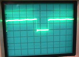
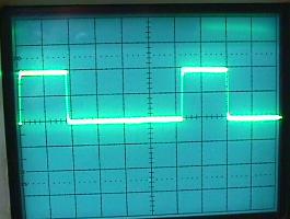
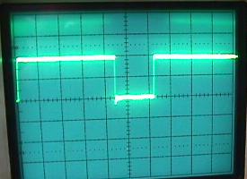
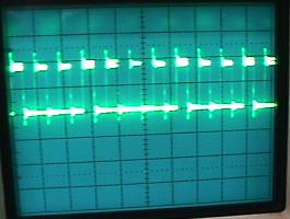
Left: Chip U9 (CPU), pin 3. Note pins 36, 37 will have the same signal pattern too. This is the clock signal. |
Middle: Chip U9 (CPU), pin 40 and pin 2. Should be a straight line "high", except initially at power-on. |
Right: Chip U9 (CPU), pin 5. This is the Valid Memory Address line. |
 |
 |
 |
|
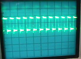
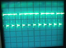
Left: U9 (CPU) pin 5, and U19 pin 8 look like this. |
Right: U19 pin 10, and U14 pin 11 look like this. |
 |
 |
|
Left: U14 pin 12, and U15 pin 4 look like this. |
Right: U15 pin 5. |
 |
 |
|
Left: U15 pin 6, and U15 pins 1 and 2 look like this. |
Right: U15 pin 3. |
 |
 |
- Check U9 (CPU) address and data lines with your logic probe for pulsing signals. This includes pins 9 to 22, 24 (address lines, pin 24 is only used if 2732 EPROMs installed) and pins 26 to 33 (data lines).
- If the PIA at U11 is bad (or its socket is bad), all the above pulses can be present and acting correctly. Yet the LED will still be stuck on. This PIA is right in the "corrosion zone", so make sure the U11 socket and chip are in good shape.
- If C23 on the solenoid driver board is not filtering the +5 volts effectively, this can cause the MPU to lock and leave the LED on (see Upgrading the Voltage Regulator/Solenoid Driver Board for details on this).
- If Q20 (the +5 voltage regulator) on the Solenoid Driver board is bad, the LED will remain on.
- H = Logic High (+5)
- L = Logic Low (GND)
- P = Pulse
- HP = High Pulse (signal is mostly high but pulsing)
- LP = High Pulse (signal is mostly low but pulsing)
- X = No signal
- TP2: should have +12 volts.
- R29: should have +12 volts on both sides of this 1/2 watt 470 ohm resistor.
- Q2: should have +11 volts on the leg closest to U11 (PIA). <-- CLAY CHECK THIS.
- Q2: Cross the two legs that are next to each other with a screw driver. The LED should come on.
- The CPU accesses, by means of input RS0, RS1, CS0, CS1 and CS2 each of the two full byte registers used to store the port initialization information. If does this, one register at a time. After it completes the first register, it repeats for the second. It goes through 256 tests similar to that used to check each byte in U7 (second flash). If each time the CPU writes a word into the register, it can read the same word back, it continues to test until completion.
- The CPU accesses, by means of input RS0, RS1, CS0, CS1 and CS2, each of two full byte registers used as data output registers when PA0 to PA7 and PB0 to PB7 are used as outputs. It does the same type of test on each register as described just above. Again if no faults are found, the test is continued until completion.
- The CPU then accesses, by means of input RS0, RS1, CS0, CS1 and CS2, the two ports CA2 and CB2. The port is initialized as an output. The port is then written into to see if it can store a "1" and then a "0".
- Check resistor R17 (150k). If this resistor goes open, or is not making good contact the circuit board, there will be no 7th flash. This resistor commonly fails.
- Check resistor R16 (2k).
- Check resistor R18 (1.5 meg).
- Check diodes CR52 and CR49 (1N4148 or 1N914).
If you've gotten to this point, and the MPU's LED is still staying lit, you may want to consider sending the board out for repair.
Strengthen the Reset Signal by Replacing Caps C14 and C15.
The two capacitors at C14 and C15 (470 pfd) should also be
replaced. If these capacitors are weak, the reset signal will not
be as crisp and strong. This is very apparent if you have a scope.
Was there Work Done on Chips U15 and U16?
If chips U15 or U16 were worked on, suspect problems.
Even though these chips are not directly involved in the reset circuit,
there are very fragile traces which travel underneath the
U15/U16 sockets. If someone replaced these chip and/or sockets,
these traces could be damaged.
Using a ohm meter and check for continuity on all of these
traces (this may require removing the U15/U16 sockets; always
replace these sockets with strip socket headers, so the
traces maybe seen and worked on easily in the future).
More on the RESET Signal and a Locked-on LED.
A major part of the reset circuit is transistor Q1, and there is an easy
way to test it. As we learned above, when the game is first turned
on, the reset line (pin 40 of the U9 CPU) goes low for just a moment,
then sticks high. You can similate a reset by shorting the
ground junction of resistors R1 and R3. This will force a reset
in a good MPU board. As you do this, watch pin 40 of U9 with your
logic probe. It should go low for a moment, then stick high.
If it doesn't, try replacing Q1 (2N3904). If Q1's collector doesn't
go to about 4 volts DC when R1/R3 junction is grounded, then Q1 is bad.
Q5 gets Cooked by R11, and the Game Re-boots Intermittently.
Another strange problem relates to transistor Q5 (2N4403). This
transistor is also part of the reset circuit (along with Q1),
and is located right below R11, an 82 ohm 2 watt power
resistor. The problem here is resistor R11 gets HOT, and is sometimes
touching Q5. The heat is transfered to Q5, and this can cause the
MPU board to suddenly stop running, and reboot the game.
To fix this, provide an air gap between Q5
and R11. You should also probably replace Q5 too. If you replace R11,
make sure you leave some "air" between R11 and the MPU board.
The Game only Starts up "sometimes".
If the MPU only starts up properely "sometimes",
replace Q1 and Q2 (both 2N3904), Q5 (2N4403), VR1 (1N959B or 1N4738A) and CR5
(1N4148 or 1N914). These transistors and diodes need to be in perfect
working order for the MPU to boot reliably.
LED Still Locked On: MPU Board Signals.
If having play problems with an otherwise working MPU,
check all the chip's
signals with a logic probe, and cross reference them to this
chart. If a signal is other than shown below, check the schematic. If it's
an input line to the chip, the device that feeds that pin is
probably bad. If it's an output line from the chip, the chip
itself is probably bad.
All the following signals are with the MPU board in "attract" mode,
and a MPU -35 loaded with Kiss 2732 EPROM's at U2 and U6.
Because these signals are with the game in attract mode, this
chart won't help much if your MPU is in some other state.
Key:
| Chip | Pin/Signal | � | Chip | Pin/Signal | ||||
|---|---|---|---|---|---|---|---|---|
| � � U16 (9602) | L 1 | 16 H | � | � � U15 (MC3459) | P 1 | 14 H | ||
| � | LP 2 | 15 L | � | � | P 2 | 13 P | ||
| � | H 3 | 14 LP | � | � | P 3 | 12 P | ||
| � | P 4 | 13 H | � | � | P 4 | 11 P | ||
| � | H 5 | 12 P | � | � | P 5 | 10 P | ||
| � | P 6 | 11 H | � | � | P 6 | 9 P | ||
| � | P 7 | 10 P | � | � | L 7 | 8 P | ||
| � | � L 8 | 9 P | ||||||
| Chip | Pin/Signal | � | Chip | Pin/Signal | ||||
|---|---|---|---|---|---|---|---|---|
| � � U20 (4502) | P 1 | 16 H | � | � � U17 (7400) | P 1 | 14 H | ||
| � | P 2 | 15 L | � | � | P 2 | 13 P | ||
| � | P 3 | 14 P | � | � | P 3 | 12 P | ||
| � | L 4 | 13 HP | � | � | P 4 | 11 P | ||
| � | LP 5 | 12 HP | � | � | P 5 | 10 P | ||
| � | P 6 | 11 LP | � | � | P 6 | 9 P | ||
| � | LP 7 | 10 P | � | � | L 7 | 8 HP | ||
| � | L 8 | 9 LP | ||||||
| Chip | Pin/Signal | � | Chip | Pin/Signal | ||||
|---|---|---|---|---|---|---|---|---|
| � � U18 (4049) | H 1 | 16 X | � | � � U19 (4011) | HP 1 | 14 H | ||
| � | P 2 | 15 P | � | � | HP 2 | 13 P | ||
| � | P 3 | 14 P | � | � | P 3 | 12 P | ||
| � | P 4 | 13 X | � | � | P 4 | 11 P | ||
| � | P 5 | 12 P | � | � | H 5 | 10 P | ||
| � | P 6 | 11 P | � | � | HP 6 | 9 H | ||
| � | HP 7 | 10 H | � | � | L 7 | 8 P | ||
| � | L 8 | 9 L | ||||||
| Chip | Pin/Signal | � | Chip | Pin/Signal | ||||
|---|---|---|---|---|---|---|---|---|
| � � U14 (4049) | H 1 | 16 X | � | � � U12 (555) | L 1 | 8 H | ||
| � | P 2 | 15 LP | � | � | HP 2 | 7 P | ||
| � | P 3 | 14 HP | � | � | HP 3 | 6 P | ||
| � | P 4 | 13 X | � | � | H 4 | 5 H | ||
| � | HP 5 | 12 P | ||||||
| � | HP 6 | 11 P | ||||||
| � | P 7 | 10 HP | ||||||
| � | L 8 | 9 P | ||||||
| Chip | Pin/Signal | � | Chip | Pin/Signal | ||||
|---|---|---|---|---|---|---|---|---|
| � � U2 (ROM) | P 1 | 24 H | � | � � U6 (ROM) | P 1 | 24 H | ||
| � | P 2 | 23 P | � | � | P 2 | 23 P | ||
| � | P 3 | 22 P | � | � | P 3 | 22 P | ||
| � | P 4 | 21 P | � | � | P 4 | 21 P | ||
| � | P 5 | 20 P | � | � | P 5 | 20 P | ||
| � | P 6 | 19 P | � | � | P 6 | 19 P | ||
| � | P 7 | 18 L | � | � | P 7 | 18 P | ||
| � | P 8 | 17 P | � | � | P 8 | 17 P | ||
| � | P 9 | 16 P | � | � | P 9 | 16 P | ||
| � | P 10 | 15 P | � | � | P 10 | 15 P | ||
| � | P 11 | 14 P | � | � | P 11 | 14 P | ||
| � | L 12 | 13 P | � | � | L 12 | 13 P | ||
| Chip | Pin/Signal | � | Chip | Pin/Signal | ||||
|---|---|---|---|---|---|---|---|---|
| � � U7 (6810) | L 1 | 24 H | � | � � U8 (5101) | P 1 | 22 H | ||
| � | P 2 | 23 P | � | � | P 2 | 21 P | ||
| � | P 3 | 22 P | � | � | P 3 | 20 P | ||
| � | P 4 | 21 P | � | � | P 4 | 19 P | ||
| � | P 5 | 20 P | � | � | X 5 | 18 P | ||
| � | X 6 | 19 P | � | � | P 6 | 17 H | ||
| � | P 7 | 18 P | � | � | P 7 | 16 P | ||
| � | P 8 | 17 P | � | � | L 8 | 15 P | ||
| � | P 9 | 16 P | � | � | P 9 | 14 P | ||
| � | P 10 | 15 P | � | � | P 10 | 13 P | ||
| � | P 11 | 14 P | � | � | P 11 | 12 P | ||
| � | P 12 | 13 P | ||||||
| Chip | Pin/Signal | � | Chip | Pin/Signal | ||||
|---|---|---|---|---|---|---|---|---|
| � � U10 (6820) | L 1 | 40 H | � | � � U11 (6820) | L 1 | 40 HP | ||
| � | P 2 | 39 HP | � | � | HP 2 | 39 LP | ||
| � | P 3 | 38 HP | � | � | H 3 | 38 HP | ||
| � | P 4 | 37 HP | � | � | P 4 | 37 HP | ||
| � | HP 5 | 36 P | � | � | P 5 | 36 P | ||
| � | P 6 | 35 P | � | � | P 6 | 35 P | ||
| � | P 7 | 34 H | � | � | P 7 | 34 H | ||
| � | P 8 | 33 P | � | � | P 8 | 33 P | ||
| � | P 9 | 32 P | � | � | P 9 | 32 P | ||
| � | HP 10 | 31 P | � | � | H 10 | 31 P | ||
| � | HP 11 | 30 P | � | � | H 11 | 30 P | ||
| � | HP 12 | 29 P | � | � | H 12 | 29 P | ||
| � | HP 13 | 28 P | � | � | H 13 | 28 P | ||
| � | HP 14 | 27 P | � | � | H 14 | 27 P | ||
| � | HP 15 | 26 P | � | � | L 15 | 26 P | ||
| � | HP 16 | 25 P | � | � | H 16 | 25 P | ||
| � | HP 17 | 24 P | � | � | H 17 | 24 P | ||
| � | LP 18 | 23 P | � | � | L 18 | 23 P | ||
| � | LP 19 | 22 P | � | � | H 19 | 22 P | ||
| � | H 20 | 21 P | � | � | H 20 | 21 P | ||
| Chip | Pin/Signal | ||
|---|---|---|---|
| � � U9 (6800) | L 1 | 40 H | |
| � | H 2 | 39 L | |
| � | P 3 | 38 L | |
| � | HP 4 | 37 P | |
| � | P 5 | 36 P | |
| � | H 6 | 35 L | |
| � | L 7 | 34 P | |
| � | H 8 | 33 P | |
| � | P 9 | 32 P | |
| � | P 10 | 31 P | |
| � | P 11 | 30 P | |
| � | P 12 | 29 P | |
| � | P 13 | 28 P | |
| � | P 14 | 27 P | |
| � | P 15 | 26 P | |
| � | P 16 | 25 LP | |
| � | P 17 | 24 P | |
| � | P 18 | 23 LP | |
| � | P 19 | 22 P | |
| � | P 20 | 21 L | |
-
The LED is Always OFF, and Never Comes On.
This can be caused by a lack of +12 volts getting to the LED, or the LED could be dead. A dead LED happens quite a bit actually. But first trace the +12 volts:
If +12 volts is at the above three points (or at least two of them), the LED is probably bad. If you have the above voltages, cross the two adjacent legs of Q2 together with a screw driver. This should light the LED. If it doesn't, and the above voltages exist, replace the LED.
Ok, the MPU's LED "Flickers": What's Next?.
At this point you have an "unlocked" MPU board. By
"unlocked" I mean you get the intial LED flicker upon power-on.
This tells us that U6, U9 and U11 are good, and the CPU is
"running". Now the MPU will test the other components on the
board. So at this point, you should have all the other socketed
chips like U7, U8, U10, U2, etc (if you removed them) back in the board.
The U6 ROM will continue to run its diagnostics on the other
components on the MPU board and will FLASH when each of its
tests are COMPLETED. What follows is a description of these
flashes (or lack of them), and what they mean.
-
1st Brief Flicker:
The Fakers Guide: If the LED briefly flickers on power-up, U6 (ROM), U9 (CPU), U11 (PIA), the reset components, and +5 volts DC are good (remember some Stern games also require the U2 and/or U5/U6 ROMs for the first flicker). If the LED locks on, one of these components (or some other supporting components such as the MPU's Q1, Q2, Q5, VR1, or C23, Q20 on the solenoid driver board) are bad (see above). Also the traces connecting these components together could be bad (battery corrosion!).
Techno Guide: On power-up, the U9 CPU chip requires +5 volts DC be applied before the reset line is allowed to swing from 0 to +4.8 volts. It also requires the presense of a two-phase, non-overlapping clock pulse. If these conditions are met, and if the U9 CPU chip itself is good, the LED on the MPU board briefly flickers.
The brief flicker indicates the operation is proper. The MPU has gone out to memory and obtained the starting address of the self-test from memory. The flicker indicates that it then went to that address and started to execute the self-test program.
The Valid Power Detectors circuit on the U9 CPU works with the +5 volts DC regulator Q20 on the solenoid driver board. This prevents the reset line from going high until +5 volts DC is proper at the U9 CPU chip. Q20 is supposed to go into regulation when +7.5 volts DC is applied to its input. This means that when the game is turned on, and a sufficient time (milliseconds) has passed so that C23 on the solenoid driver board has charged, Q20 switches into regulation. This supplies +5 volts DC to the MPU board.
Q1 on the MPU board (in the valid power detector circuit) does not allow the CPU chip to turn on immediately. The zener diode VR1, in series with the base of Q1 delays application of the reset voltage until C23 charges. At this point, Q1 and Q5 on the MPU board go into conduction, and the reset line at the MPU is caused to go high. Only then is the U9 CPU chip "on".
The importance of the Valid Power Detection circuit can be appreciated when the following fact is known; should the reset line be allowed to go high before the +5 volts is applied and proper, or should the +5 volt supply fail and go out of regulation, the U9 CPU chip can jump out of the program. The reason this happens is that the U9 CPU goes out to the program memory bank U1-U6 for instructions. The logic levels are wrong because the +5 volts is not proper. The MPU misinterprets the data, jumps out of the program, and executes this misinterpreted program! The U9 CPU is now like a train that has left the tracks, and it can end up anywhere. The difference is that a train will eventually stop. But the U9 CPU may continue as long as the clock circuit continues to run.
If the U9 CPU jumps out of the program, it is said to be in "run away". While it is mis-interpreting the program, it invariably overwrites the Bookkeeping function in U8 and the scratch pad RAM. An indication of a "run away" would be false data in bookkeeping. Probable cause is a faulty Q20 or C23 (or both) on the solenoid driver boared, or a leaky zener diode VR1 on the MPU board.
First Flash:
The Fakers Guide: No first flash means one of the game
program ROMs U1 to U6 is bad. Could be a mis-jumpered board,
or a bad ROM chip at U1 to U6.
Techno Guide: the U9 CPU chip next goes out to the program ROM's (read only memory) U1 to U6. It tests each chip in the bank, in accordance to how the MPU board is jumpered. When it finds the bank is correct, it flashes the LED for the first flash. A fault in the U1 to U6 ROM chips is indicated by the absense of the first flash.
The U9 CPU tests each ROM chip's function like this: in a game with ROM chips U2 and U6 (typical), the CPU first goes to U2. It fetches the first byte in U2, and adds it to the second byte in U2. It will add to this sum the third byte in U2. This continues until all bytes in the chip have been added up. If the sum of all the bytes is "0000 0000", the U9 CPU proceeds to U6 and repeats this process. If U6 has a sum of "0000 0000", the U9 CPU causes the LED to flash the first time. Fault in either U2 or U6 is indicated by the absence of the first flash.
The contents of each ROM chip have byte locations called checksums, reserved for this test routine. There is one checksum byte reserved in each 512 bytes of ROM memory. The game programmer at Bally must insert a btye with the proper value in each checksum byte location to force each 512 byte checksum to equal "0000 0000".
During the life of an electronic game, if a ROM chip U1 to U6 fails by so much as a single bit, it will be detected during this CPU test. The CPU will not continue until the defective ROM chip is replaced.
Second Flash:
The Fakers Guide: no second flash means U7 (6810) is bad.
Techno Guide: The U9 CPU chip goes out to the U7 RAM and erases the contents of the first byte (U7 is a 128 byte scratch pad memory). It then tries to read back the word "0000 0000" (indicating erased). If it can read it back, it adds "1" and continues. 256 tries later, it writes the word "1111 1111". If it can read it back, it has determined that the first byte in U7 is good. It repeats this process for each of the 128 bytes of RAM in U7, one at a time. If at the end of this 256 x 128 (=32,768) tests, each time the CPU writes, it can read the same word back, the CPU cause the LED to flash a second time.
Note the pause between the first and second flashes. This is the CPU doing 32,768 tests to the RAM at U7 and repeats the process.
Third Flash:
The Fakers Guide: no third flash means U8 (5101) is bad.
Techno Guide: The U9 CPU goes out to U8 (CMOS 5101 RAM) and makes a copy of the contents of the first half byte. It does this because U8 is battery supplied, non-volatile memory where the bookkeeping functions are stored. It then erases the contents of the first half byte, and tries to read back the word "0000 xxxx". If it can read it back, it adds "1" to the previous word (giving "0001 xxxx"). It continues to write and read until it reaches the word "1111 xxxx". When this is done successfully, the CPU restores the original contents to the first byte located in U8. It then makes a copy of the contents of the second byte, and repeats the process. It does this for the entire 256 bytes, one at a time. If at the end of the 256 x 16 (=4096) test, each time the CPU writes and reads the same word correctly, the CPU caused the LED to flash a third time.
Fourth Flash:
The Fakers Guide: no fourth flash means U10 (6821 PIA) is bad.
Techno Guide: The U9 CPU chip now tests the first 6821 PIA chip. There are two of these chips on the MPU board, which are identical and interchangable. The test for both is the same.
To determine if a PIA chip is good, the U9 CPU does the following:
Fifth Flash:
The Fakers Guide: no fifth flash means U11 (6821 PIA) is bad.
Techno Guide: Same test is performed on U11 as was performed on U10. See above.
Sixth Flash*:
The Fakers Guide: no sixth flash means either PIA U11 (6821)
is bad, or U12 (555) timer is bad.
Techno Guide: The U9 CPU chip monitors PIA2, port CA1 (U11). If transitions from high to low are detected, the CPU decides the Display Interrupt Generator is working. If U12, a 555 timer, or any associated circuit component fails, the CPU will not flash the LED the sixth time.
* Note on Baby Pacman and Granny and the Gators, this flash step is skipped and not tested.
Seventh Flash**:
The Fakers Guide: no seventh flash means PIA U10 (6821) is bad, or
there is no +43 volts DC for the solenoids (power transformer fuse F4 is
probably blown), or U14 is bad.
Techno Guide: The U9 CPU chip monitors PIA1 port CB1 (U10). If transistion from high to low are detected, the CPU decides that the zero crossing detector is working. If U14 fails and the CB1 line is stuck high or low, the test will also fail. The zero crossing detector circuit input is the +43 volts DC line that is used for the solenoids. If the fuse in that line (F4 on the power transformer module) is blown when the game is turned on, the CPU will not flash the LED the seventh time.
** Note on Baby Pacman and Granny and the Gators this flash is the final flash. These games only had six flashes instead of seven.
Game Initialization.
The U9 CPU chip now initializes the two PIA's U10 and U11, assigning
to each port its role as either an input or an output, as required.
It then clears out U7 (6810 RAM). Now the CPU takes a picture of the
settings of fixed switches S1 to S32 on the MPU board. It stores this
"picture" in memory in chip U7. The CPU next jumps to a routine which
turns on the "Game Over" feature light, lights the "Ball in Play"
light, and the "Credit Indicator" light if there are credits stored
in memory. It resets the drop targets and activates the saucer kickers
or any kicker associated with a playfield device that can trap
the ball and keep it out of the outhole. It then energizes the coin
lockout solenoid to allow the game to accept coins (unless the credit
maximum was met). Playfield and backbox feature lights
associated with and appropriate to animation effects are turned on.
With the game tested and initialized, the CPU now divides its time
between monitoring momentary switches for closure (coin switch, credit
button) and updating displays (lamps and score registers).
Problems/Solutions with the Seventh Flash.
If fuse F4 is blown on the solenoid board, the seventh flash
will not occur. But what if there is a problem on the playfield which
is forcing this fuse to blow (stopping the final LED flash on the MPU board,
hence stopping your MPU diagnostics)?
The easiest way to deal with this is to remove the solenoid connectors from the solenoid driver board to the playfield. These connectors are on the left side of the solenoid driver board, and the one connector at the bottom right of the board too. This should allow the F4 fuse to be replaced, and the completion of the MPU booting process.
To help find the playfield coil that is causing the F4 fuse to blow, replace the connectors one at a time on the solenoid driver board (with the game off), and reboot the game. This will help issolate the bad coil.
Another thing to try: remove the under-the-playfield coil fuse, and replace fuse F4. If F4 does not blow, then one of the coils under the playfield is somehow shorted or staying energized (and blowing the solenoid driver F4 fuse). If fuse F4 still blows, there is either a problem with the backbox knocker, or the cabinet coin door lockout coil, the solenoid bridge rectifier (on the rectifier board), or the rectifier board's varister.
Also try removing connectors J1 and J3 from the rectifier board (this moves the solenoid power back a step further, not allowing it to get any further than the rectifier board). Replace fuse F4 on the solenoid driver board, and turn the game on. If the fuse still blows, the solenoid bridge rectifier (on the rectifier board) or the rectifier board's varister is probably at fault.
If it is a coil under the playfield, check the coils to see which one energizes when the game is powered on. Or disconnect a wire on each solenoid, and re-attach each wire, one at a time, until the fuse blows. At this point it could be the coil, coil diode, or coil driver transistor at fault.
Still No Seventh Flash - Other Things to Check.
First check TP3 and make sure there is 21 volts DC (of
course this assumes fuse F4 is not blown on the solenoid board).
If there is still no seventh flash, here are some other things to check.
Remember all the components mentioned
below are in the battery corrosion area.
MPU Boots Fine, but after Turning Off and Immediately back On, The MPU board
is Locked.
Game is turned on and works fine. Then the game is
turned off, and within a few minutes, turned back on. But the MPU board's LED is
locked on, and will not (flicker) boot. The reset section of the MPU board has
been rebuilt, as described in this document.
The first thing to suspect is MPU battery corrosion in the reset circuit. Inspect the board for any damage due to corrosion. The problem may be the reset line stays high from the battery power. When the battery is discharged enough, the game will restart. This can happen from the two 8.2k resistors (R1, R3) at the bottom of the MPU board. Other resistors in the reset section should be checked too (R2, R112, R120, R140, R139, R138, R140, R12, R11).
Seven Flashes Constantly Repeats.
The MPU boots and gets to the 7th flash, then start all over
and repeats the seven flashes, then starts all over and does it over and over.
This can happen from a bad 6810 RAM at U7. Or possibly a bad socket at U7.
3c. When things don't work: Game ROMs, EPROMs, and Jumpers - the Basics
-
Bally started using the improved -35 MPU board from 1979 to 1985.
The later -35 MPU board can be used
for ANY game from 1977 to 1985. The difference between the new -35 MPU
and the early -17 MPU is mostly how the game ROMs are used and addressed (though
the manufacturing and the type of sockets in the earlier -17 boards
is also considered inferior to the -35 MPU boards). This section will
address general concepts that are used on both the -17 and -35 (and -133)
MPU boards.
Bally has provided us with about 35 different "jumper" locations on the -35 (and -133) MPU board, and about ten on the -17 MPU. This was done to handle all the different game ROM (read only memory) chip configuations, for all the different games. Depending on supply and demand for certain ROM chips, Bally pretty much had all the bases covered. They could use any combination of ROM types and sizes to fit their needs.
Important: Before you Change any Jumpers!!
It is EXTREMELY important that you have a working MPU board
before you change any jumper locations! If you MPU board
currently has ROMs in it, get it working first before you play
with the jumpers. If you have your MPU board jumpered incorrectly
for the game ROMs installed, the diagnostic LED light will stay
on and the board will not power-up. So it is absolutely important
that the jumpers are correct for the ROMs installed. Get your
MPU board working first before proceeding.
Which MPU board Is It: -17 or -35 or -133? (How to Tell!)
Of course Bally silkscreen the MPU part number (AS-2518-17 or
AS-2518-35 or AS-2518-133) right on the MPU board. But sometimes
due to battery corrosion, etc, the part number can not be read.
It is important to know which board is being worked on, as the
game ROM/EPROM jumpers are different.
Basically there are two flavors of MPU board: the -17 or -35 (the -133 is really a -35 board with R113 changed to a diode CR52). The easiest way to tell which board is to examine connector J5. On a -17 MPU board, this connector will have 32 pins (including the removed "key" pin). On a -35/-133 MPU board, J5 will have 33 pins (including the removed "key" pin).
Bally/Williams' Jumper Information.
Though I personally don't recommend or use it, here is a link to the information
that (recently) Williams posted about the original Bally board jumpers.
You may find this information helpful (though personally I don't). It lives at
ballyrm1.htm.
Masked ROMs versus EPROMs.
If you are repairing a game, you may be replacing the original masked
(black) ROMs. These ROMs, as they get old, break very easily. In particular
their pins tarnish and/or break off. The black tarnish is silver oxide,
which is caused by oxygen and moisture in the air, and dis-similar
metal electrolytic action between the silver plated pins and the tin
plated sockets. The black oxide doesn't conduct well, and this can
make the ROMs stop working correctly. They are not available any more,
but they can be replaced with EPROMs.
EPROMs are basically the same as masked ROMs, but have a small cyrstal window on top of the chip. If UV (ultra-violet) light is shined through this window, the chip can be erased and re-programmed. An EPROM programmer is necessary to re-program an EPROM. These attach to your computer (though there are some stand alone ones too), and can "burn" a blank EPROM with a game's program code. After the EPROMs are burned, a sticker is placed over their window to prevent light from erasing them. EPROMs are the best replacement for your old and tired black masked ROMs.
Chances are if you are doing any repairs to a Bally MPU board, and you need new game ROMs, you will be installing EPROMs. EPROMs are available blank from many sources. But you need to have them "burned" first before you can use them.
|
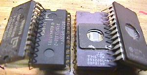
The two chips on the left are the black "masked" ROMs. All masked ROMs used in these Bally games are known as "9316" EPROMs can be 2516, 2716, 2732, or 2532. The last two numbers identifies the size of the ROM (16k or 32k bits of program data). Masked ROMs are only usable in the game they were designed for. Note how their legs are tarnished black. The two chips on the right are EPROMs. Note the "window" which allows them to be erased, and re-programmed. Also note how the EPROM's legs are not tarnished. You can just read the notation on the one EPROM as "2532". |
|
-
The Program Code that Lives inside the ROMs.
The memory inside each ROM or EPROM is the heart of your game. It contains the power-on diagnostics, the switch matrix, the game rules, and the coil assignments, among other things. Each model of pinball game has different program code that must be installed only in the game it is designed for. The program code is stored (burned) in your game's ROMs or EPROMs.
The Jumpers.
Each kind and size of ROM chip has its own set of enable and address
requirements. To allow a board to use any type or size ROM that
Bally had in stock, jumpers were used on the MPU board.
It also provides a way to take a MPU board out of a
newer game, and put it in an older game (and only have to
change the jumpers and the game ROMs).
The wide array of jumpers Bally provides is very confusing. Some games use just one ROM at U6. Others use three ROMs at U6, U2, and U1. The size and type of these individual chips can change too.
What Type and Size are My ROM chips?
Before you can change a MPU board's jumpers to another game
(or for new EPROMs), you need to know the type and size of
chips you are installing. If you are installed Masked ROMs,
these are all 9316 (16k bits of data) or 9332 (32k bits of data).
If you are installing
EPROMs, you need to read the markings on the EPROM. They will
say what type and size of EPROM you have. They will be 2516,
2716 (both 2516 and 2716 are the same type of 16k bit EPROM),
2532, or 2732 (32k bit EPROMs). Note the jumpers for 2532 and 2732 EPROMs are
different, as these chips have different pin assignment (but the
jumpers for 2532 EPROMs and 9332 ROMs are the same, which is the
ONLY sharing of masked ROM and EPROM jumpers). This
is unlike 2516 EPROMs and 2716 EPROMs, which are identical and have
identical jumpers.
What if I don't have an EPROM Programmer?
You can also buy the above EPROM chips already programmed
in 2732 format (or any other size) from
Tom Callahan
for a nominal fee. Just drop him a line and tell him what
you want.
Using 2532 EPROMs instead of 9332 Masked ROMs.
If the game in question is a later Bally game with 9332 masked
ROMs, these can be changed to 2532 EPROMs with NO jumper modifications!
This can be handy and convenient if the original black 9332 masked
ROMs need changing, but the repair person doesn't want to mess
with the jumpers.
What Do the Masked ROMs Chip Numbers Mean?
If the game in question uses original black masked ROMs,
there are numbers on the ROMs that denote information about
the chip. This information is can be seen by clicking
ballyro2.htm, where
the ROM numbers are sort numerically. Another page located at
ballyrom.htm shows the
same information, but sorted by game name.
Also shown are the original jumper settings.
Note the higher -xx number means a later revision. In the case of the U6 chips, that revision is important, as generally a game can not be run with the "wrong" U6 part. But for the U1/U2 chips, it usually means a later version of the same game (and all the chips must be of the "correct" revision to match the others, though there's not always a good way to know what that is).
As an example, Lost World uses "720-28" for U6. But then the other chips should all be "729-xx", with the latest revision being "729-33" at U1, and "729-48" at U2. If the game has an earlier version, they would have some other numbers after "729-". But note there can be no mixing of old and new versions!
* Go to the Bally Repair Guide Part 1
* Go to the Bally Repair Guide Part 3
* Go to the Pin Fix-It Index
* Go to Marvin's Marvelous Mechanical Museum at http://marvin3m.com